www.medlicott.eu/pmltd


Composite Flywheel
Background
Philip Medlicott was the inventor and designer of the composite high speed flywheel (EP 0 145 182) that ran inside the BP KESS (kinetic energy storage system) vehicle regenerative braking system, developed between 1980 and 1986. Although the BP development is over 35 years old, the technology and experience is still highly relevant. The BP KESS technology was abruptly discontinued as a consequence of the changing market conditions arising from the sudden fall in the oil price in the mid 80's which removed much of the fuel savings incentive provided by a regenerative braking system. However, the increases in fuel prices since then, the need to reduce the carbon footprint and exhaust emissions has resulted in renewed interest in flywheel technology.
Design concept
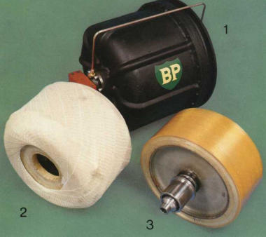
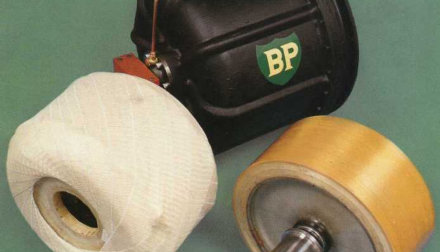
The flywheel hub design provided an innovative solution to enable the high radial strain experienced by the flywheel rim to be coupled with the relatively small strain found at the shaft. The 1.44 MJ (400 Whr), 460 mm diameter, 16,000 rpm composite flywheel design was extensively modelled with FE and validated by spin testing. Other work concentrated on addressing rotor dynamics and the design of the support system to enable the flywheel to operate above the critical speed. The flywheel rotor was supported in the horizontal plane between two sets of matched ball bearings which themselves were located on squeeze film dampers. The flywheel was run inside an innovative containment system which provided a means to withstand the high temperatures and radial loads produced during the containment event.
System description
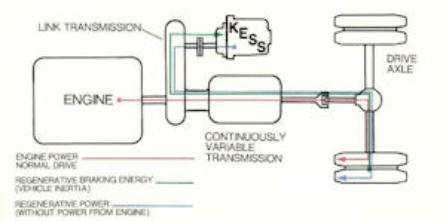
The flywheel and containment system operated inside an outer case, which also provided a means to support the external gearbox. A rotating magnetic seal on the end of the flywheel shaft enabled the rotor to be run under vacuum to minimise aerodynamic drag. The system incorporated a microprocessor based monitoring system to detect the possible early onset of flywheel failure by monitoring vibration, vacuum, bearing temperature etc. The manufacture of the flywheel system was based on quantity production methods to enable a reasonable pay back time on the bases of savings in operating cost. A subsequent analysis of the manufacturing costs for the prototype showed that this could be achieved. The above schematic shows how the flywheel system was coupled to an early version of the Torrotrack continuously variiable transmission system.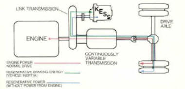
Testing
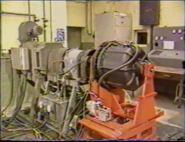
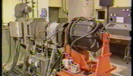
The system was subjected to several thousand hours (50,000 cycles) of endurance testing on a test rig where it was cycled between 8,000 and 16,000 rpm. In addition tests were carried out with rotors, some deliberately damaged, at speeds up to 25,800 rpm to try to initiate a catastrophic failure. In all cases the failure was initiated by a dynamic instability and resulted in a benign failure mode, i.e. the rim remained essentially intact, which was an in keeping with the system design philosophy. Finally the system was tested on a test track to demonstrate its compatibility with a bus (16 tonne) environment, for example shock loads from uneven road surfaces. These tests also included cornering tests at the maximum flywheel design speed to determine the sensitivity of the flywheel vibration characteristics to large gyroscopic forces.


medlicott.eu/pmltd

Composite
Flywheel
Background
Philip Medlicott was the inventor and designer of the composite high speed flywheel (EP 0 145 182) that ran inside the BP KESS (kinetic energy storage system) vehicle regenerative braking system, developed between 1980 and 1986. Although the BP development is over 35 years old, the technology and experience is still highly relevant. The BP KESS technology was abruptly discontinued as a consequence of the changing market conditions arising from the sudden fall in the oil price in the mid 80's which removed much of the fuel savings incentive provided by a regenerative braking system. However, the increases in fuel prices since then, the need to reduce the carbon footprint and exhaust emissions has resulted in renewed interest in flywheel technology.
Design concept
The flywheel hub design provided an innovative solution to enable the high radial strain experienced by the flywheel rim to be coupled with the relatively small strain found at the shaft. The 1.44 MJ (400 Whr), 460 mm diameter, 16,000 rpm composite flywheel design was extensively modelled with FE and validated by spin testing. Other work concentrated on addressing rotor dynamics and the design of the support system to enable the flywheel to operate above the critical speed. The flywheel rotor was supported in the horizontal plane between two sets of matched ball bearings which themselves were located on squeeze film dampers. The flywheel was run inside an innovative containment system which provided a means to withstand the high temperatures and radial loads produced during the containment event.
System description
The flywheel and containment system operated inside an outer case, which also provided a means to support the external gearbox. A rotating magnetic seal on the end of the flywheel shaft enabled the rotor to be run under vacuum to minimise aerodynamic drag. The system incorporated a microprocessor based monitoring system to detect the possible early onset of flywheel failure by monitoring vibration, vacuum, bearing temperature etc. The manufacture of the flywheel system was based on quantity production methods to enable a reasonable pay back time on the bases of savings in operating cost. A subsequent analysis of the manufacturing costs for the prototype showed that this could be achieved. The above schematic shows how the flywheel system was coupled to an early version of the Torrotrack continuously variiable transmission system.
Testing
The system was subjected to several thousand hours (50,000 cycles) of endurance testing on a test rig where it was cycled between 8,000 and 16,000 rpm. In addition tests were carried out with rotors, some deliberately damaged, at speeds up to 25,800 rpm to try to initiate a catastrophic failure. In all cases the failure was initiated by a dynamic instability and resulted in a benign failure mode, i.e. the rim remained essentially intact, which was an in keeping with the system design philosophy. Finally the system was tested on a test track to demonstrate its compatibility with a bus (16 tonne) environment, for example shock loads from uneven road surfaces. These tests also included cornering tests at the maximum flywheel design speed to determine the sensitivity of the flywheel vibration characteristics to large gyroscopic forces.