www.medlicott.eu/pmltd

FRP Liner JIP (2)
System and long term testing
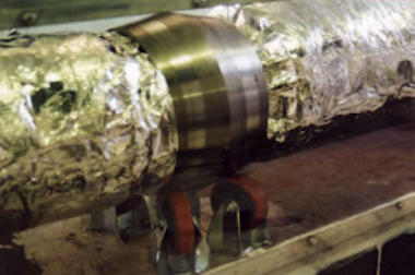
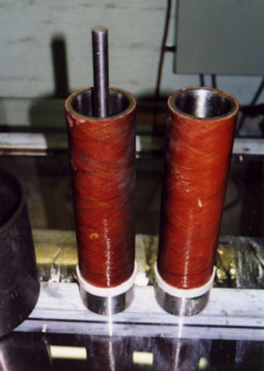
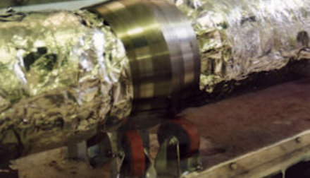
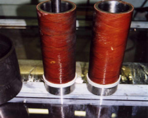
Long term exposures of system components was carried out which included the grout and corrosion barrier ring. The FRP material was supplied in two forms: • Free-standing (double sided exposure), 86 mm ID tube specimens of 7 materials (including a vinyl ester glass sample) • Composite tube (single sided exposure), 150 mm ID FRP tubes bonded into standard 7” 29lb/ft C steel tubulars. After assembly the tubulars were subject to temperature, pressure, tension and bending loads to simulate installation. In each test, two of the sections were manufactured using a phenolic grout to provide the high temperature performance. One of the sections was lined with the glass epoxy liner, the other with the carbon epoxy liner. In the early tests two additional 2 m long sections had a glass epoxy liner but manufactured using a cementitious grout. An example of the end connection detail is shown to the right. In addition, a sequence of exposures to typical down hole chemicals was included to investigate for possible synergistic interactions. The exposures were carried out on a set of 86 mm diameter samples for comparison with specimens exposed for a similar length of time to brine and hydrocarbons but with no exposure to the chemicals. Further details of the chemicals are given below: • Chem 1: hypochlorite biocide added to brine at 250 ppm chlorine concentration • Chem 2: 15%HCl/10%methanol mixture, with inhibitor added to the acidizing treatment at 2% • Chem 3: Scale inhibitor added to brine at 10% by volume • Chem 4: Scale dissolver at 50% concentration in fresh water. • Chem 5: Biocide in brine at 250 ppm • Chem 6: 9% formic acid solution On completion of the final exposure, the rig was allowed to rapidly decompress while still at elevated temperature over about 10 minutes. The glass epoxy materials exhibited severe blistering resulting in exposed fibres. One of the glass epoxy liners also exhibited severe collapse damage indicative of buckling after the first production fluid exposure. This suggests there may be a limit of axial swelling that can be tolerated. In contrast, none of the carbon reinforced epoxy or phenolic materials show any consistent deterioration in mechanical properties with time, although the visual observations indicate that a degree of surface degradation does take place with time. These materials showed no evidence which would indicate that exposure to the chemical environments contributed to a further degradation in performance.
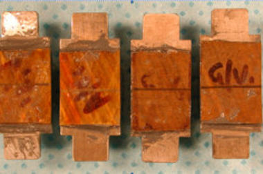
Galvanic corrosion
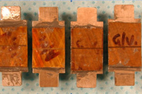
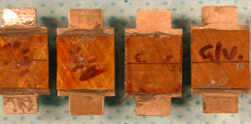
The purpose of this task was to determine whether significant galvanic corrosion may occur between a FRP lined carbon steel tubular and a coupling(s) or accessories made using CRA materials. It also considered the possible effect that the electrically conductive carbon fibre reinforcement in the liner may have on galvanic corrosion. The test set-up comprised a composite liner applied to the external surface of a steel tube. To simulate in-service damage, the FRP liner had a 6mm dia. hole drilled in it to allow direct contact of the carbon steel with the production environment. The galvanic cell was set up inside the FRP tubing assembly to avoid possible premature failure of the tubing assembly if the CRA component, e.g. coupling, was applied in the conventional manner. The results of testing showed that: Galvanically enhanced corrosion had not occurred with the material couples and configuration used in these tests. The FRP successfully protected the C steel surface for the duration of the exposure. The evidence of a reducing corrosivity with exposure time shows that the duplex steel CRA did not significantly affect a carbon steel free surface only 75 mm from its boundary. The lack of corrosion product on the sealing face of the PTFE insert suggests the successful protection of the carbon steel from the test environment. This is also true of the glass epoxy FRP liner, despite the poor performance of this material in the mechanical test evaluations of the degradation
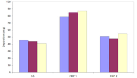
Scale deposition/removal and wax
deposition on FRP
The experimental programme involved studying the deposition of calcium carbonate (CaCO3), barium sulphate (BaSO4) and wax from supersaturated solutions onto the surface of types types of fibre reinforced polymers and a stainless steel (UNS S31603). The extent of scale and wax deposited after a given period was compared for the three different surfaces. In addition, the tenacity of the scale once deposited was assessed through tests involving an impinging jet of liquid directed at varying velocities at the surface of the samples. It was shown that the extent of scale is invariably smaller on FRP than on stainless steel and very little difference between the glass epoxy (amine harderner) and glass phenolic could be determined. The scale formed on the stainless steel was found to be more difficult to remove than that formed on the FRP. It can be concluded from these results that it is unlikely that use of FRP liners would promote severe problems due to scaling where SS is already used. The ease of removal of scale from FRP would be advantageous. A large difference in the extent of wax deposition between the two types of FRP was observed with the glass phenolic material showing more deposition than on the stainless steel under identical conditions. This is opposite to what is often assumed as FRP will undoubtedly be insulating and will reduce the temperature driving force which is thought to be the key point associated with wax deposition. The glass phenolic exhibited just slightly more deposition than the stainless steel. In some final tests the deposition on an IPD cured FRP material was assessed and it was shown to be comparable with the results of the glass phenolic material.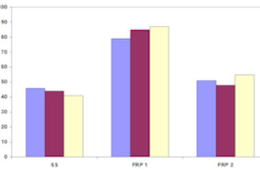
Abrasion testing
Testing was carried out to quantify the abrasion resistance of glass epoxy, carbon epoxy and carbon silica modified phenolic materials from wirelining at conditions typical of service environments at elevated temperature. Testing was carried out on both virgin and material that had been conditioned in high temperature production environment and at three temperatures, 25°C, 100°C and 160°C. However not all materials were tested at all these conditions. The test rig subjected the inside surface of the 25x20mm rectangular liner test samples to a reciprocating wear action by the 3.175mm diameter (125) 435Hv slick line steel wire. The total contact force was 80 N equivalent to 4 N/mm and the mean velocity was about 0.5 m/s (to give a peak of about 0.7 m/s). This compares with typical wireline speeds of 100 ft/min (0.51 m/s). The virgin carbon epoxy material was subject to 3 sets of wear tests at 25°C. These corresponded to wireline distances of 1,000 m, 5,000 m and 10,000 m. From this an indication of the wear characteristics was made. Testing of the remaining test samples was carried out using the 1,000 m test duration. The results are summarised as follows: • The carbon-epoxy showed little effect of conditioning on the wear resistance. • The carbon phenolic material showed a significant reduction of wear resistance due to conditioning but still performed better than carbon epoxy FRP. • The wear behaviour measured suggests initial losses are dominant and are associated with the resin characteristics The superior wear performance of the carbon phenolic at the 160°C elevated temperature was expected but it is surprising that carbon phenolic also proved more robust at ambient temperature. Past jet impingement tests of glass phenolic have generally shown phenolic to be much more brittle and to have high erosion rates compared to glass epoxy. On the issue of the severity of the test the most pertinent factor relevant to the short time scale of these tests is likely to be the viscosity and adsorption behaviour onto the surfaces and the effect this would have on wear of the resin. The lubrication properties of a crude oil would be anticipated to be superior to that provided by the test fluid hydrocarbon. The test could therefore contain a second level of conservatism in the result obtained; the first being the possible effect of distance over which the results were obtained.


medlicott.eu/pmltd
FRP Liner JIP (2)
System and long term
testing
Long term exposures of system components was carried out which included the grout and corrosion barrier ring. The FRP material was supplied in two forms: • Free-standing (double sided exposure), 86 mm ID tube specimens of 7 materials (including a vinyl ester glass sample) • Composite tube (single sided exposure), 150 mm ID FRP tubes bonded into standard 7” 29lb/ft C steel tubulars. After assembly the tubulars were subject to temperature, pressure, tension and bending loads to simulate installation. In each test, two of the sections were manufactured using a phenolic grout to provide the high temperature performance. One of the sections was lined with the glass epoxy liner, the other with the carbon epoxy liner. In the early tests two additional 2 m long sections had a glass epoxy liner but manufactured using a cementitious grout. An example of the end connection detail is shown to the right. In addition, a sequence of exposures to typical down hole chemicals was included to investigate for possible synergistic interactions. The exposures were carried out on a set of 86 mm diameter samples for comparison with specimens exposed for a similar length of time to brine and hydrocarbons but with no exposure to the chemicals. Further details of the chemicals are given below: • Chem 1: hypochlorite biocide added to brine at 250 ppm chlorine concentration • Chem 2: 15%HCl/10%methanol mixture, with inhibitor added to the acidizing treatment at 2% • Chem 3: Scale inhibitor added to brine at 10% by volume • Chem 4: Scale dissolver at 50% concentration in fresh water. • Chem 5: Biocide in brine at 250 ppm • Chem 6: 9% formic acid solution On completion of the final exposure, the rig was allowed to rapidly decompress while still at elevated temperature over about 10 minutes. The glass epoxy materials exhibited severe blistering resulting in exposed fibres. One of the glass epoxy liners also exhibited severe collapse damage indicative of buckling after the first production fluid exposure. This suggests there may be a limit of axial swelling that can be tolerated. In contrast, none of the carbon reinforced epoxy or phenolic materials show any consistent deterioration in mechanical properties with time, although the visual observations indicate that a degree of surface degradation does take place with time. These materials showed no evidence which would indicate that exposure to the chemical environments contributed to a further degradation in performance.
Galvanic corrosion
The purpose of this task was to determine whether significant galvanic corrosion may occur between a FRP lined carbon steel tubular and a coupling(s) or accessories made using CRA materials. It also considered the possible effect that the electrically conductive carbon fibre reinforcement in the liner may have on galvanic corrosion. The test set-up comprised a composite liner applied to the external surface of a steel tube. To simulate in-service damage, the FRP liner had a 6mm dia. hole drilled in it to allow direct contact of the carbon steel with the production environment. The galvanic cell was set up inside the FRP tubing assembly to avoid possible premature failure of the tubing assembly if the CRA component, e.g. coupling, was applied in the conventional manner. The results of testing showed that: Galvanically enhanced corrosion had not occurred with the material couples and configuration used in these tests. The FRP successfully protected the C steel surface for the duration of the exposure. The evidence of a reducing corrosivity with exposure time shows that the duplex steel CRA did not significantly affect a carbon steel free surface only 75 mm from its boundary. The lack of corrosion product on the sealing face of the PTFE insert suggests the successful protection of the carbon steel from the test environment. This is also true of the glass epoxy FRP liner, despite the poor performance of this material in the mechanical test evaluations of the degradation
Scale deposition/removal
and wax deposition on FRP
The experimental programme involved studying the deposition of calcium carbonate (CaCO3), barium sulphate (BaSO4) and wax from supersaturated solutions onto the surface of types types of fibre reinforced polymers and a stainless steel (UNS S31603). The extent of scale and wax deposited after a given period was compared for the three different surfaces. In addition, the tenacity of the scale once deposited was assessed through tests involving an impinging jet of liquid directed at varying velocities at the surface of the samples. It was shown that the extent of scale is invariably smaller on FRP than on stainless steel and very little difference between the glass epoxy (amine harderner) and glass phenolic could be determined. The scale formed on the stainless steel was found to be more difficult to remove than that formed on the FRP. It can be concluded from these results that it is unlikely that use of FRP liners would promote severe problems due to scaling where SS is already used. The ease of removal of scale from FRP would be advantageous. A large difference in the extent of wax deposition between the two types of FRP was observed with the glass phenolic material showing more deposition than on the stainless steel under identical conditions. This is opposite to what is often assumed as FRP will undoubtedly be insulating and will reduce the temperature driving force which is thought to be the key point associated with wax deposition. The glass phenolic exhibited just slightly more deposition than the stainless steel. In some final tests the deposition on an IPD cured FRP material was assessed and it was shown to be comparable with the results of the glass phenolic material.
Abrasion testing
Testing was carried out to quantify the abrasion resistance of glass epoxy, carbon epoxy and carbon silica modified phenolic materials from wirelining at conditions typical of service environments at elevated temperature. Testing was carried out on both virgin and material that had been conditioned in high temperature production environment and at three temperatures, 25°C, 100°C and 160°C. However not all materials were tested at all these conditions. The test rig subjected the inside surface of the 25x20mm rectangular liner test samples to a reciprocating wear action by the 3.175mm diameter (125) 435Hv slick line steel wire. The total contact force was 80 N equivalent to 4 N/mm and the mean velocity was about 0.5 m/s (to give a peak of about 0.7 m/s). This compares with typical wireline speeds of 100 ft/min (0.51 m/s). The virgin carbon epoxy material was subject to 3 sets of wear tests at 25°C. These corresponded to wireline distances of 1,000 m, 5,000 m and 10,000 m. From this an indication of the wear characteristics was made. Testing of the remaining test samples was carried out using the 1,000 m test duration. The results are summarised as follows: • The carbon-epoxy showed little effect of conditioning on the wear resistance. • The carbon phenolic material showed a significant reduction of wear resistance due to conditioning but still performed better than carbon epoxy FRP. • The wear behaviour measured suggests initial losses are dominant and are associated with the resin characteristics The superior wear performance of the carbon phenolic at the 160°C elevated temperature was expected but it is surprising that carbon phenolic also proved more robust at ambient temperature. Past jet impingement tests of glass phenolic have generally shown phenolic to be much more brittle and to have high erosion rates compared to glass epoxy. On the issue of the severity of the test the most pertinent factor relevant to the short time scale of these tests is likely to be the viscosity and adsorption behaviour onto the surfaces and the effect this would have on wear of the resin. The lubrication properties of a crude oil would be anticipated to be superior to that provided by the test fluid hydrocarbon. The test could therefore contain a second level of conservatism in the result obtained; the first being the possible effect of distance over which the results were obtained.